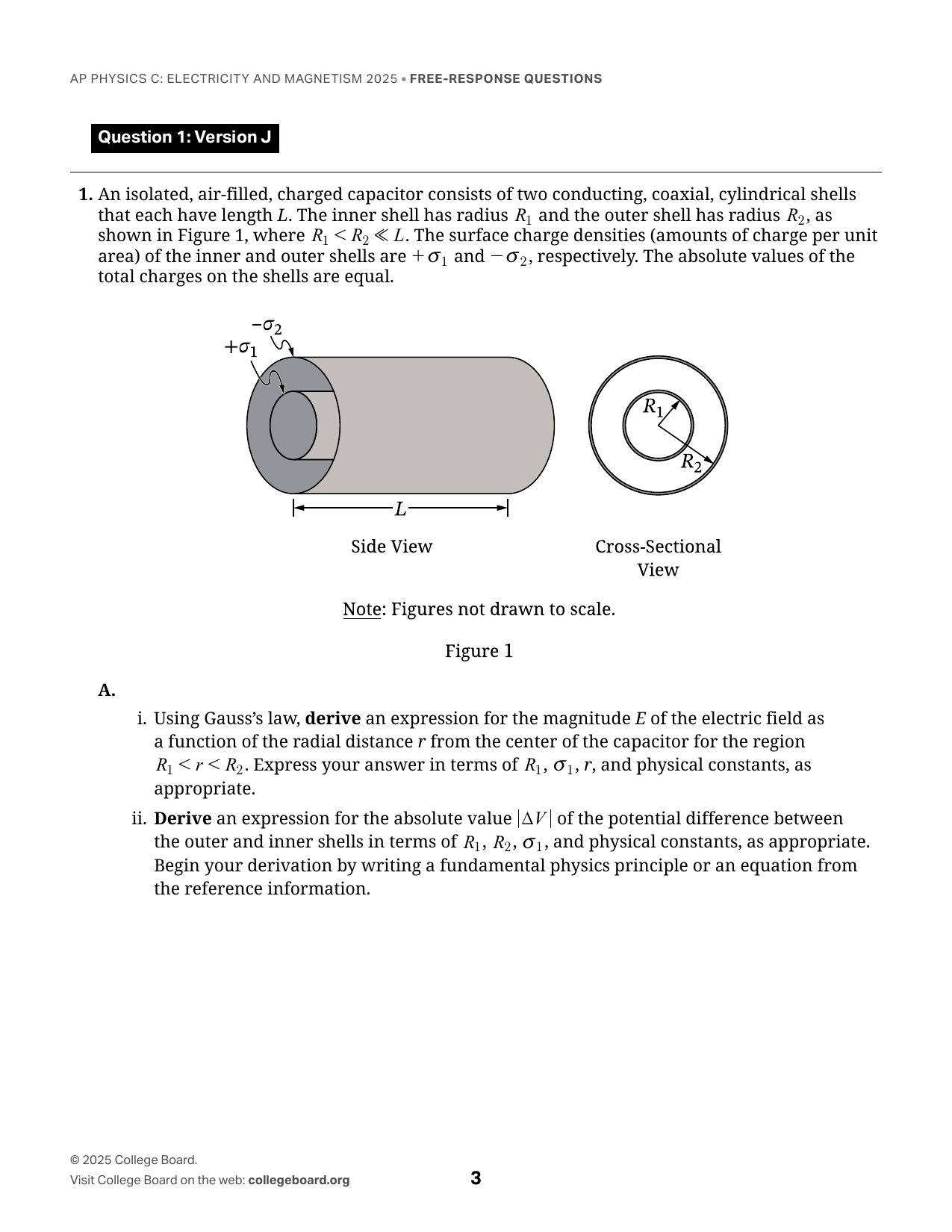
Question 1: Version J 1. An isolated, air-filled, charged capacitor consists of two conducting, coaxial, cylindrical shells that each have length L. The inner shell has radius R₁ and the outer shell has radius R₂, as shown in Figure 1, where R₁ ≪ R₂ ≪ L. The surface charge densities (amounts of charge per unit area) of the inner and outer shells are +σ₁ and −σ₂, respectively. The absolute values of the total charges on the shells are equal. Figure 1: Side View and Cross-Sectional View of the cylindrical shells, labeled +σ₁, −σ₂, L, R₁, and R₂. Note: Figures not drawn to scale. A. i. Using Gauss’s law, derive an expression for the magnitude E of the electric field as a function of the radial distance r from the center of the capacitor for the region R₁ < r < R₂. Express your answer in terms of R₁, σ₁, r, and physical constants, as appropriate. ii. Derive an expression for the absolute value |ΔV| of the potential difference between the outer and inner shells in terms of R₁, R₂, σ₁, and physical constants, as appropriate. Begin your derivation by writing a fundamental physics principle or an equation from the reference information. iii. On the axes shown in Figure 2, sketch a graph of E as a function of r from r = 0 to a position that is outside the outer shell. Figure 2: Axes showing E as a function of r, with marked positions R₁ and R₂. B. A material of dielectric constant κ is inserted into the isolated, charged capacitor such that the material fills the region R₁ < r < R₂, as shown in Figure 3. Figure 3: Cross-Sectional View showing the dielectric material labeled κ filling the region R₁ < r < R₂, with radii R₁ and R₂. Derive an expression for the capacitance C of the capacitor with the material inserted in terms of L, R₁, R₂, κ, and physical constants, as appropriate. Begin your derivation by writing a fundamental physics principle or an equation from the reference information.
Draw, drag, resize. Advanced coordinates are available if needed.
Question 2: Version J 2. A rotating, circular, conducting loop of area A and resistance R is in an external uniform magnetic field of magnitude B that is directed in the -z-direction. At time t = 0, the magnetic field is perpendicular to the plane of the loop, as shown in Figure 1. The loop is rotating with constant angular speed ω and period T about the dashed line that is along the diameter of the loop. The value of the magnetic flux through the loop as a function of time t is Φ = BA cos(ωt). Figure 1 shows the circular conducting loop rotating about a dashed diameter in a magnetic field B directed into the page, with coordinate axes +x, +y, and +z. A. The absolute value of the induced emf in the loop is |ε|. The partially completed bar chart in Figure 2 shows a bar that represents |ε| at t = 3/4 T. In Figure 2, draw bars to represent |ε| at times t = 0, 1/4 T, and 1/2 T relative to |ε| shown at 3/4 T. If |ε| = 0, write a “0” in that column. Figure 2 shows a bar chart with columns labeled t = 0, 1/4 T, 1/2 T, and 3/4 T; the 3/4 T column is partially completed. B. Derive an expression for the maximum induced current in the loop in terms of A, R, B, ω, and physical constants, as appropriate. Begin your derivation by writing a fundamental physics principle or an equation from the reference information. C. On the axes shown in Figure 3, sketch a graph of the instantaneous power P dissipated by the loop as a function of t during the time interval 0 ≤ t ≤ T. Figure 3 provides axes for P as a function of t, with t = 0 at the origin, t = 1/2 T marked at the midpoint, and t = T at the right endpoint. D. Indicate whether the sketch you drew in part C is or is not consistent with the bars that you drew in part A. Briefly justify your answer by referencing the functional dependence between P and |ε|.
Draw, drag, resize. Advanced coordinates are available if needed.
3. In Experiment 1, students are asked to use a graph to determine the resistivity ρ₁ of a circuit element that is connected to a variable power supply, as shown in Figure 1. The circuit element is cylindrical and has uniform resistivity. The students have access to a voltmeter, an ammeter, and a ruler. Figure 1: Circuit diagram showing a variable power supply connected in a circuit with a cylindrical circuit element. A. Describe a procedure for collecting data that would allow the students to use a graph to determine ρ₁, including any steps necessary to reduce experimental uncertainty. B. Describe how the collected data could be graphed and how that graph would be analyzed to determine ρ₁. In Experiment 2, the students are asked to use a graph to determine the resistivity ρ₂ of solid, cylindrical resistors made of the same material but of different lengths L. The cross-sectional area of each resistor is 5.0 × 10⁻⁶ m². The students directly measure the resistance R between the ends of each resistor. Table 1 provides L and R for each resistor. Table 1 L (m) | R (Ω) 0.010 | 0.90 0.020 | 1.6 0.030 | 2.5 0.040 | 3.2 0.050 | 4.0 C. i. Indicate two quantities, either measured quantities from Table 1 or additional calculated quantities, that could be graphed to produce a straight line that could be used to determine ρ₂. Vertical axis: ______ Horizontal axis: ______ ii. On the grid provided, create a graph of the quantities indicated in part C (i). • Use Table 2 to record the measured or calculated quantities that you will plot. • Clearly label the axes, including units as appropriate. • Plot the points you recorded in Table 2. [Graph grid provided] iii. Draw a best-fit line for the data graphed in part C (ii). D. Using the best-fit line that you drew in part C (iii), calculate an experimental value for ρ₂.
Draw, drag, resize. Advanced coordinates are available if needed.
4. Long, parallel wires S and T are a distance 2d apart. Both wires carry equal currents I, but the currents are in opposite directions. Both wires are parallel to the x-axis. At the instant shown in Figure 1, Sphere 1 is a distance d above Wire S, Sphere 2 is a distance d below Wire S, and both spheres are moving with speed v in the +x-direction. Each sphere has positive charge +Q. Gravitational effects are negligible. Figure 1: Wire S is above Wire T, with the wires separated by 2d. Wire S carries current I in the +x-direction, and Wire T carries current I in the −x-direction. Sphere 1, with charge +Q, is a distance d above Wire S and moves with velocity v in the +x-direction. Sphere 2, with charge +Q, is a distance d below Wire S and moves with velocity v in the +x-direction. The axes shown have +x to the right, +y upward, and +z out of the page. A. F₁ is the magnitude of the magnetic force exerted on Sphere 1 due to the currents in wires S and T. F₂ is the magnitude of the magnetic force exerted on Sphere 2 due to the currents in wires S and T. Indicate whether F₂ is greater than, less than, or equal to F₁ by writing one of the following. • F₂ > F₁ • F₂ < F₁ • F₂ = F₁ Justify your answer. B. Derive an expression for the magnitude B_tot of the magnetic field at the location of Sphere 2 due to the currents in wires S and T in terms of d, I, and physical constants, as appropriate. Begin your derivation by writing a fundamental physics principle or an equation from the reference information. C. Later, Wire T carries current 3I in the +x-direction. At the instant shown in Figure 2, Sphere 2 is a distance d below Wire S and is moving with speed v in the +x-direction. F_new is the new magnitude of the magnetic force exerted on Sphere 2 due to the currents in wires S and T. Figure 2: Wire S is above Wire T, with Sphere 2 between them. Wire S carries current I in the +x-direction, and Wire T carries current 3I in the +x-direction. Sphere 2, with charge +Q, is a distance d below Wire S and a distance d above Wire T, and moves with velocity v in the +x-direction. The axes shown have +x to the right, +y upward, and +z out of the page. Indicate whether F_new is greater than, less than, or equal to F₂ by writing one of the following. • F_new > F₂ • F_new < F₂ • F_new = F₂ Briefly justify your answer by referencing your derivation in part B.
Draw, drag, resize. Advanced coordinates are available if needed.
This material is the intellectual property of College Board, is not owned by GradeThis, and is shown here for ease of use and demonstration purposes.