2025 AP Physics 2: Algebra-Based Free-Response Questions
Advanced PlacementAP Physics 2Free ResponseScience
4 questions40 pts
4 gradable40 rubric criteria0 dependencies
q1Question 1
q1
Question 1
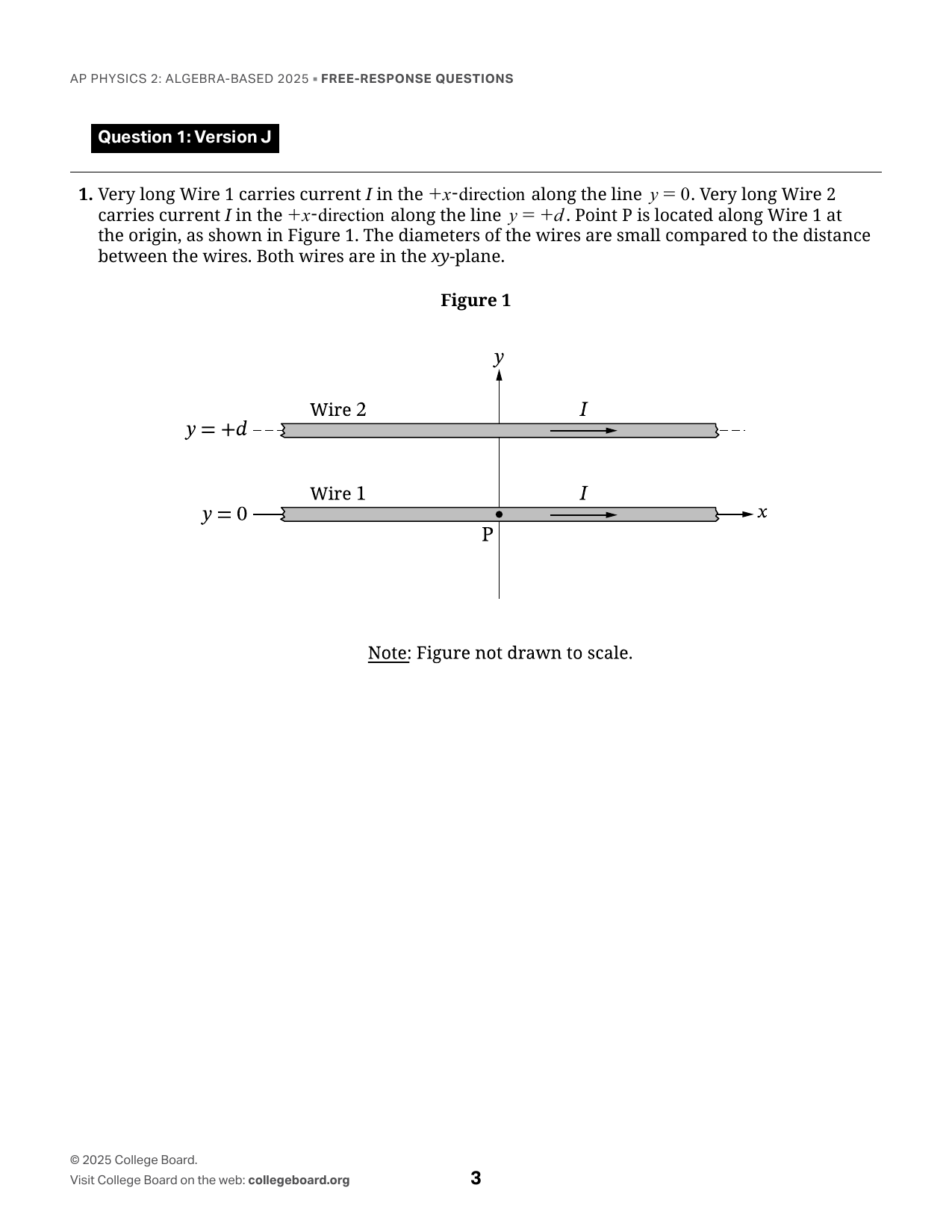
Question 1: Version J 1. Very long Wire 1 carries current I in the +x-direction along the line y = 0. Very long Wire 2 carries current I in the +x-direction along the line y = +d. Point P is located along Wire 1 at the origin, as shown in Figure 1. The diameters of the wires are small compared to the distance between the wires. Both wires are in the xy-plane. Figure 1 Note: Figure not drawn to scale. A. i. Complete the following tasks in figures 2 and 3. Use either arrows or the symbols shown in the box above the figures for your response. • Indicate the direction of the magnetic field from Wire 2 at Point P in Figure 2. • Indicate the direction of the magnetic force that is exerted on Wire 1 by Wire 2 in Figure 3. Symbols X Into the page ● Out of the page Magnetic Field from Wire 2 at Point P Magnetic Force on Wire 1 by Wire 2 Figure 2 Figure 3 ii. Very long Wire 3 carrying current 2I in the +x-direction is placed in the xy-plane along the line y = y3. The net magnetic force exerted on Wire 1 by the currents in wires 2 and 3 is zero. Derive an expression for y3 in terms of d. Begin your derivation by writing a fundamental physics principle or an equation from the reference information. B. Wire 3 is moved very far away from wires 1 and 2. A circular conducting loop in the xy-plane is initially held at rest below Wire 1. The loop is then moved at a constant speed in the −y-direction, as shown in Figure 4. Figure 4 Note: Figure not drawn to scale. Indicate whether there is a clockwise induced current in the loop, a counterclockwise induced current in the loop, or no induced current in the loop. ___ Clockwise ___ Counterclockwise ___ There is no induced current in the loop. Justify your answer.
Rubric Criteria (10)
A1Indicates that the magnetic field is directed into the page in Figure 2.
1.0000pts
A2Indicates either that the magnetic force is directed in the +y-direction in Figure 3, or that if the field direction is out of the page in Figure 2, the magnetic force is directed in the −y-direction in Figure 3.
1.0000pts
A3Provides a multistep derivation that includes B = μ₀I/(2πr), ΣF = 0, an equivalent listed equation, or another relevant equation. Vector notation is not required.
1.0000pts
A4Gives the magnitude of the magnetic field from Wire 2 along Wire 1 as B₂ = μ₀I/(2πd), or an equivalent expression.
1.0000pts
A5Substitutes 2I for the relevant current term in an expression for the magnetic field from Wire 3 along Wire 1 or for the magnetic force exerted on Wire 1 by Wire 3.
1.0000pts
A6Equates the magnitudes of the magnetic fields from Wires 2 and 3 along Wire 1, or equates the corresponding force-per-unit-length magnitudes, consistently with A5.
1.0000pts
A7Gives the correct position of Wire 3, y₃ = 2d, or an equivalent expression.
1.0000pts
B1Indicates that the induced current in the loop is clockwise.
1.0000pts
B2Indicates that the magnetic field or magnetic flux due to currents in Wires 1 and 2 is directed into the page inside the loop.
1.0000pts
B3Correctly relates the decrease in the absolute value of the magnetic flux as the loop moves away from the wires to an induced magnetic field directed into the page, applying Lenz’s law consistently with B2.
1.0000pts
Dependencies (0)
Page Mapping (3)
Visual Preview
5 boxes
Draw, drag, resize. Advanced coordinates are available if needed.
1
2
3
4
5
Select a box to edit its role and metadata.
Attribution
This material is the intellectual property of College Board, is not owned by GradeThis, and is shown here for ease of use and demonstration purposes.